How to Choose the Right CT Ratio for Your Electrical Panel
Selecting the correct current transformer (CT) ratio is one of the most critical steps in designing an electrical distribution panel, switchgear, or substation. A poorly sized CT can lead to inaccurate metering, failure of protective relays, or even catastrophic component damage during short circuits.
In this guide, we break down the engineering principles and step-by-step calculations required to select the optimal CT ratio for your panels.
1. What is a CT Ratio?
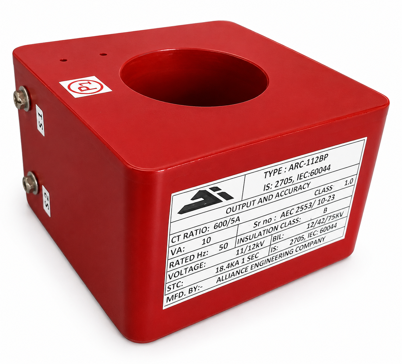
A Current Transformer (CT) scales down high primary currents (e.g., hundreds of amperes flowing in a busbar) to a standardized, low secondary current (typically 1A or 5A) that can be safely measured by panel meters and monitored by protection relays.
The CT ratio is expressed as Primary Current (Ip) / Secondary Current (Is). For example, a 2500/5A CT ratio means that when 2500 Amperes flow through the primary busbar, exactly 5 Amperes will be induced in the secondary winding.
2. Choosing the Primary Current Rating (Ip)
The primary current rating of the CT should be chosen based on the full-load current of the circuit, future expansion plans, and standard industry ratios.
The 120% Rule of Thumb
For standard metering applications, the primary current of the CT should be selected to be approximately 110% to 120% of the maximum nominal load current of the circuit.
- If the nominal current is too low relative to the CT primary rating, the CT will operate in the lower, less accurate part of its curve.
- If the nominal current is too high relative to the CT primary rating, the CT may saturate during peak load, leading to inaccurate readings and overheating.
Standard Ratios
Always round up your calculated primary current to the nearest standard CT rating (e.g., 50A, 100A, 150A, 200A, 250A, 300A, 400A, 500A, 600A, 800A, 1000A, 1200A, 1600A, 2000A, 2500A).
*Example:* If your maximum nominal load current is 360A, multiplying by 1.2 gives 432A. The next standard primary current rating is 400A or 500A. In this case, choose a 400/5A or 500/5A CT depending on expansion plans.
3. Selecting the Secondary Current Rating (Is): 1A vs 5A
Standard secondary current ratings are 1 Ampere and 5 Amperes. The choice between them is primarily determined by the physical distance between the CT and the metering/protection devices.
| Feature | 5A Secondary | 1A Secondary |
|---|---|---|
| Typical Distance | Very short (inside the same panel). | Long (CT in substation yard, meter in control room). |
| Lead Burden (Losses) | High lead wire losses (I²R = 25 × R). | Low lead wire losses (I²R = 1 × R). |
| Cable Size | Requires thicker copper conductors. | Allows thinner, cost-effective wiring. |
- Choose 5A if the meters and CTs are housed within the same panel suite (lead length < 10 meters).
- Choose 1A if the CT is in a switchyard or remote outdoor panel, and the cabling must run to a central control room.
4. Metering CTs vs. Protection CTs
A common mistake is using a single CT for both billing-grade metering and protection relays. They have fundamentally opposite performance requirements:
Metering CTs (Accuracy Focus)
- Goal: High accuracy during normal load conditions (5% to 120% of rated current).
- Saturation behavior: Must saturate at relatively low currents (typically Instrument Security Factor, FS < 5 or FS < 10) to protect delicate digital meters from damage during high-current fault events.
- Accuracy Classes: Class 0.2S, Class 0.2, Class 0.5S, Class 0.5 (as per IS 2705 and IEC 61869-2).
Protection CTs (Overcurrent/Fault Focus)
- Goal: Maintain linearity and avoid saturation during severe short-circuit conditions so protective relays can accurately trip the breakers.
- Saturation behavior: Must not saturate until currents reach 10x, 15x, or 20x the nominal rating (referred to as Accuracy Limit Factor, ALF).
- Accuracy Classes: 5P10, 5P20, 10P10, 10P20 (e.g., 5P20 means ±5% composite error at 20 times the rated primary current).
5. Calculating the Burden (VA)
The CT must be rated to supply enough power to drive the connected load. This load is called the Burden and is measured in Volt-Amperes (VA).
The total burden is the sum of:
- Device Burden: The input impedance of connected meters, relays, and indicators.
- Lead Burden: The resistance of the copper wire connecting the CT secondary terminals to the devices.
Formula for Lead Resistance Burden
Where:
- *Is* is the secondary current (1A or 5A).
- *R_wire* is the total loop resistance (go and return path) of the connection cables.
For a 5A secondary CT with a loop resistance of 0.2 Ω:
If the total burden (meters + leads) is 7.5 VA, you should choose a standard CT rated for 10 VA or 15 VA burden. Selecting a burden that is too high (e.g., using a 30 VA CT for a 2 VA load) can actually reduce accuracy under light loads.
Summary Checklist for Panel Engineers
- Calculate maximum nominal load current (Imax).
- Determine Primary Current (Ip): Round Imax × 1.2 up to the nearest standard primary rating.
- Choose Secondary Current (Is): Use 5A for local panel installations; use 1A for long-distance outdoor yards.
- Confirm the CT Role: Specify Class 0.5S/0.5/0.2 for metering, and Class 5P10/5P20 for protective relays.
- Calculate Connected Burden (VA): Factor in meter specs and round up to standard VA ratings (e.g. 5VA, 10VA, 15VA, 30VA).
Need built-to-spec current transformers for your upcoming project? The Alliance Engineering design team specializes in manufacturing custom LT and HT CTs up to 2500/5A with Class 0.5 accuracy. Contact our Chandigarh facility at info@allianceengineeringco.com for drawing validations.